Reinforced concrete is the most commonly used structural material in engineering construction. Although concrete is strong in resisting compressive stress, it is weak intention. Hence to withstand tensional stresses, steel is need in concrete. The reinforcement in concrete may be simple bars or rods bend and tied to a given schedule with stirrups. The nominal diameters of bars used at site were Y10, Y12, Y16, Y20, Y25 and R6.
Steel is supplied in two basic types.
1. Mild steel (250 N/mm2)
2. Tor steel (460 N/mm2)
Engineering drawings is a language to communicate with details. Therefore there is a standard to indicate reinforcement in drawing such as,
5Y10- 001- 150:-Which means 5 Number of Tor steel, 10mm Diameter, Bar mark 001, At 150mm CRS. At bottom face.
Bar location can be vary as follows:
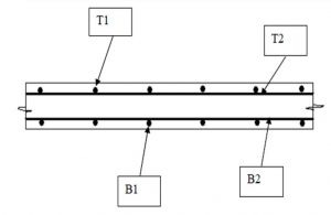
Notation for Slab-
T1 -Top outer layer, T2 -Top second layer
B1 -Bottom outer layer, B2 -Bottom second layer
While prepared the bar schedule, we used the unit weight of reinforcement bar.
Table- Unit weight of the bar
It is necessary to be careful about length when preparing bar schedules. In case of bending, bar length will increased at the bending positions.
R/f bars are jointed with using wires which is called “binding wires”. Hackers are used to bind these wires.
Cover Blocks
E.g-
Footing
Size – 1000 x 1000 x 250
R/f Details – Y10 at 225 C/C (B) Both ways

E.g- (Anchorage length 45 d (for top bars),12 d (for bottom bars)) where “d”, “Ø” is diameter of the Bar.
Anchorage length Calculation
E.g.:- 20 mm diameter bar
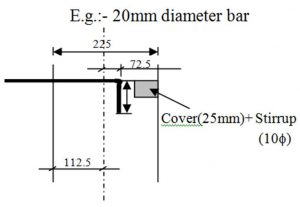
Fig 9: Anchorage length
Bending length = 112.5- (Cover (25 mm)+ Stirrup (10 Ø))
= 72.5mm
Anchorage length (x) = 45 x diameter of the bar(20 Ø)
= 827.5 mm
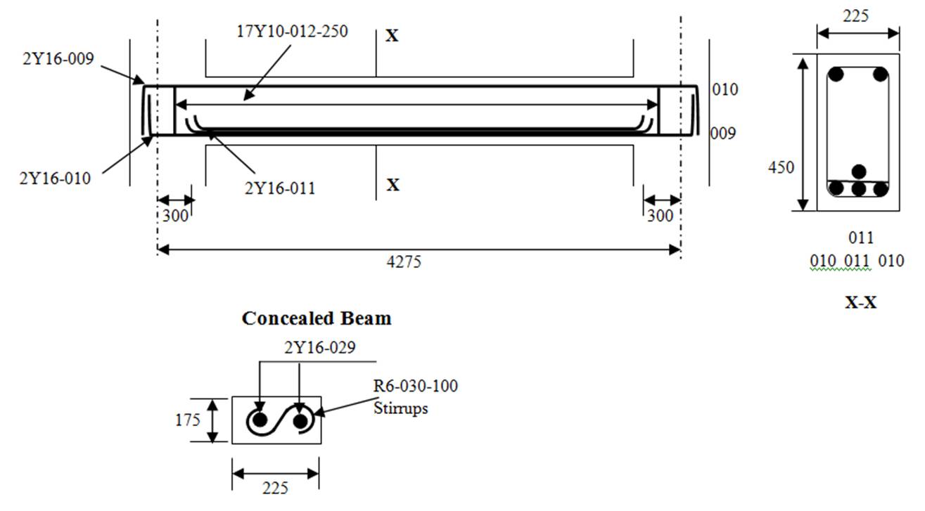
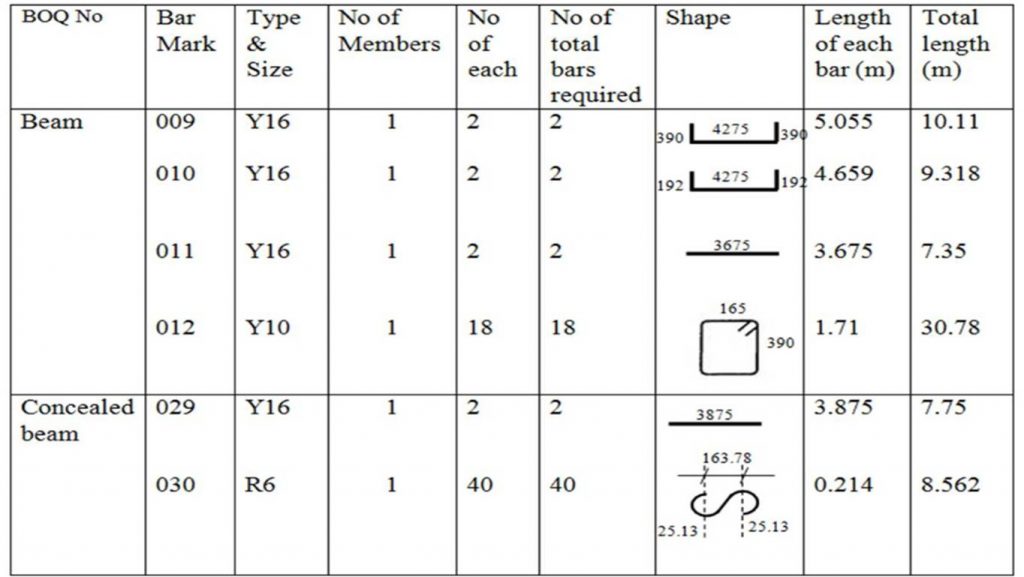
Bar schedule for Beam
First step of the fixing of slab reinforcement was placed the bottom most R/F (B1) of the slab. Before placing the re-bar, correct spacing given in the detailing drawing were marked by using piece of choke on the slab formwork. After placed the (B1) R/F then placed the (B2) R/F and bound both R/F layers together by using binding wire. Then cover blocks for bottom most R/F were fixed. Finally, Top R/F (T2), Topmost R/F (T1)& distribution bars were placed according to the drawing and fixed together by using binding wire. Then Stools were fixed to separate the both top & bottom R/F net as fulfilled the thickness.

Steel is supplied in two basic types.
1. Mild steel (250 N/mm2)
2. Tor steel (460 N/mm2)
- Bar code
Engineering drawings is a language to communicate with details. Therefore there is a standard to indicate reinforcement in drawing such as,
5Y10- 001- 150:-Which means 5 Number of Tor steel, 10mm Diameter, Bar mark 001, At 150mm CRS. At bottom face.
Bar location can be vary as follows:
Notation for Slab-
T1 -Top outer layer, T2 -Top second layer
B1 -Bottom outer layer, B2 -Bottom second layer
- Cutting and Bending of Bars
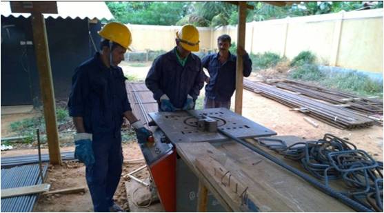
There is a steel yard in the site for storing, cutting and bending of bars. Reinforcement bars are cut into required lengths and bent into required shapes shown on the bar schedule either manually or by means of machinery.
In manual operations, laborers used the bar bending bench on which strong nails are fixed and GI pipes with suitable lengths to bend the bars. That is used for smaller diameter bars. For bending of larger diameter bars, bar bending machine is used. After bending all reinforcement bars were bundled and clearly numbered according to the bar mark so that steel fixers will not face any difficulty when fixing them.

Fig.1 :- Bar bending work
- Prepare bar schedule (important considerations)
Reinforcement Bar Schedule is prepared in a standard manner. The bar bending schedule should be prepared and it should be submitted to the steel bar steel yard to cut and to bend the bars for purposes, because bar bending schedule is the simplest of details what is in the drawings which can easy to under stand for bar benders. It contains all the details needed for fabrication of steel.Those details are bar mark, bar type and size, number of units, length of a bar, shape code, distance between stirrups (column, plinth, beam) etc.
Advantages of the Bar Schedule:- By preparing a bar schedule, and arranging them according to the lengths, it will lead to an economical bar cutting, reduce the bar cutting wastages.
- It is easy to manage the reinforcement stock required for identified time duration.
- It will help to fabrication of R/F with structure.
While prepared the bar schedule, we used the unit weight of reinforcement bar.
| Nominal Diameter of the bar (mm) | Unit weight (kg/m) |
| R6 | 0.222 |
| R10 | 0.610 |
| T10 | 0.617 |
| T12 | 0.888 |
| T16 | 1.580 |
| T20 | 2.469 |
| T25 | 3.858 |
| T32 | 6.313 |
It is necessary to be careful about length when preparing bar schedules. In case of bending, bar length will increased at the bending positions.
- Minimization of bar cutting wastage
- Off cuts of larger diameter (25mm) bars-for spacer bars
- Off cuts of smaller diameter (10mm) bars-for stools
- Lapping
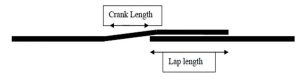
Lapping is required when a bar isn’t long enough or a joint is required. Bars may be deliberately left short for constructability and transportation concerns. The preferred method of lapping where the two bars overlap each other for some minimum distance. This distance is called Lap length. These two bars are in physical contact and wired together. It does not represent an actual bend in the bar.

Fig 2: Lapping and cranking detail
- Other material used In Reinforcement Works
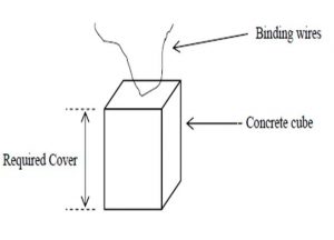
R/f bars are jointed with using wires which is called “binding wires”. Hackers are used to bind these wires.
Cover Blocks
They were made up of 1:3 ratio of cement mortar. Cover blocks should be immersed in water for 28 days to get the maximum strength.All the beams were checked to ensure adequate cover blocks are provided to the bottom and sides of the beam reinforcement. Main bars of the columns were adjusted to ensure the covering requirements before concreting. Stools of correct height were used to maintain the require gap between top and bottom reinforcement nets and cover blocks were also provided to bottom reinforcement.

Fig 3: Cover blocks
Cover to Reinforcement
- Concrete cover for steel bar is much necessary to protect the steel against corrosion (rusting) and to provide resistance against fire.
- For R.C.C. Slab and staircase the cover is 20 mm.
- For RCC column the cover (To stirrups) 30mm.
- In case of underground structures the cover is 50 mm.
- In case of beams in superstructure (To stirrups) the cover is 25mm.
- In case of ground resting floor slab (Top surface) and retaining walls the cover is 50m.
- Stirrups
Stirrups will be required at areas of high shear, such as bearing points and below large point loads. Increasing concrete beam spans, to reduce the need for additional piers, has resulted in the need for the use of steel stirrups. Concrete beams vary in depth. The deeper the beam, the more shear capacity. When the depth is not adequate, steel stirrups must be added to increase the shear capacity of the beam.
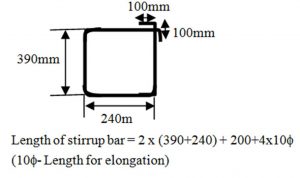
These stirrups are usually one piece of steel that is bent into a rectangular shape. The stirrup typically wraps around the bottom and top bars of the beams. A designer should specify the size, spacing and location along the length of the beam where the stirrups are required. In my site specify the stirrup dimensions in our section drawings, so that the stirrup can be manufactured prior to installation. The installer should be careful to fabricate the stirrup from one piece of steel and adequately overlap each end.

Fig 4: Bar Schedule for stirrups
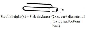
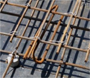
- Stools

Fig 5: Stools
Important points to be checked.
- Size of the bar
- Length of the bar
- Location of the bar
- Position of the bar
- Number of bars
- Lap lengths
- Correct cover of reinforcements and cover blocks
- Spacing (in slab reinforcements and stirrups)
- Direction of the bars (in slabs)
- Dimensions of the element thickness of a slab, depth and width of a beam, etc…)
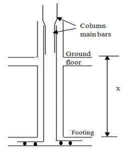
- Column Reinforcement
The column reinforcement bars should be stared from the Footing. The upper column reinforcement bars are cranked at the laps and connected. Special care should be taken in this to ensure the lap lengths. After erection of main reinforcements, cover blocks were attached to column reinforcements to maintain the required cover for column reinforcement. Most of Columns centers were located at intersections of grid lines.
Stirrup spacing
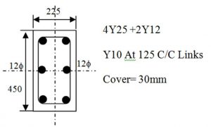
According to the Column reinforcement details drawing the reinforcement detail for a typical internal Column, from to basement to ground floor is as follows.
Column stirrups were tightened up to beam bottom level and rest is tightened once beam reinforcement is fabricated. So Bar benders was instructed how to provide the stirrups. Mark the stirrup spacing from the basement floor level in the Column main bars with a chalk as follow the detail drawing.
E.g.:

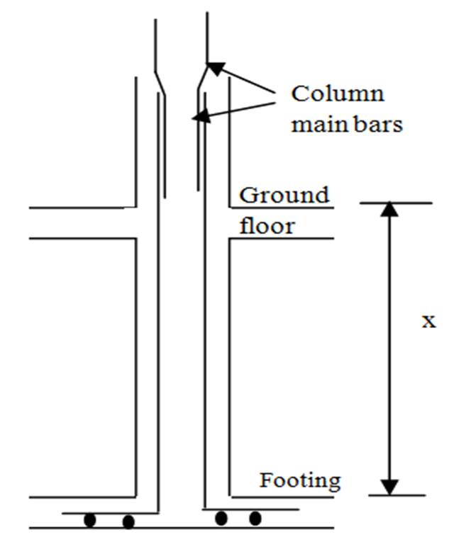
Fig 6: Section of column Reinforcement
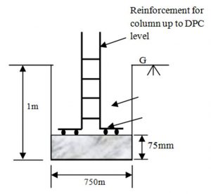
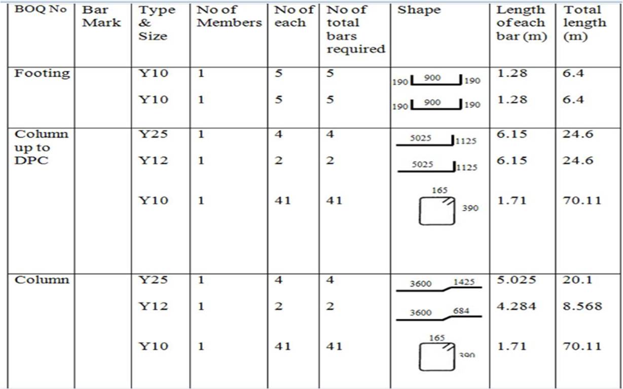
Bar Schedule for Footing, Column up to DPC and Column.E.g-

Footing
Size – 1000 x 1000 x 250
R/f Details – Y10 at 225 C/C (B) Both ways

Table 1: Schedule for Footing, Column up to DPC and Column
- Beam Reinforcement
Beam is a horizontal structural member resting on two or more supports. It is used to transfer the load to the columns.Beam reinforcements are arranged after the construction of beam and slab formwork.
The method adopted for the arrangement of beam reinforcements is as follows:
First the top most reinforcement bars are hung over the beam formwork and then the stirrups are placed and bound at correct positions. Thereafter the bottom reinforcement bars are placed and bound to the stirrups. After that the rest of the reinforcement bars and tension bars are inserted into the cage according to structural drawings. Then cover blocks are fixed to bottom and side reinforcements before placing the concrete.
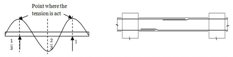
Consideration for give lap length

Fig 7: Reinforcement for beams
Top reinforcement of the beam shall be lapped at the middle of the span of between two supports. Bottom reinforcement of the beam shall be lapped at the end of the span of the two supports. Considering the region where the maximum bending movement is existing.
Lapping is did the place which the tension is didn’t act. Normally 2/3 of the length is choosing for lapping. When lapping top & bottom re-bar, it is better to follow the following method.Otherwise, it might cause to reduce the concrete covering thickness of the topmost& bottom most slab reinforcement.
Fig 8: Reinforcement for beams
Anchorage (bond) in concrete
Because the actual bond stress varies along the length of a bar anchored in a zone of tension. The main requirement for safety against bond failure is to provide a sufficient extension of the length of the bar beyond the point where the steel is required to develop its yield stress and this length must be at least equal to its development length. However, if the actual available length is inadequate for full development, special anchorages must be provided, such as bends, hooks.E.g- (Anchorage length 45 d (for top bars),12 d (for bottom bars)) where “d”, “Ø” is diameter of the Bar.
Anchorage length Calculation
E.g.:- 20 mm diameter bar

Fig 9: Anchorage length
Bending length = 112.5- (Cover (25 mm)+ Stirrup (10 Ø))
= 72.5mm
Anchorage length (x) = 45 x diameter of the bar(20 Ø)
= 827.5 mm
Bar schedule for Beam


Table 2: Bar Schedule for Beam
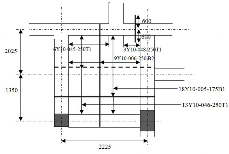
- Slab Reinforcement
Distribution bar reinforcement
Small diameter bars, usually at right angles to the main reinforcement, intended to spread a concentrated load on a slab and to prevent cracking.Standard method used for indicated the slab top & bottom reinforcement.
First step of the fixing of slab reinforcement was placed the bottom most R/F (B1) of the slab. Before placing the re-bar, correct spacing given in the detailing drawing were marked by using piece of choke on the slab formwork. After placed the (B1) R/F then placed the (B2) R/F and bound both R/F layers together by using binding wire. Then cover blocks for bottom most R/F were fixed. Finally, Top R/F (T2), Topmost R/F (T1)& distribution bars were placed according to the drawing and fixed together by using binding wire. Then Stools were fixed to separate the both top & bottom R/F net as fulfilled the thickness.

Fig 10: Reinforcement of a slab
Bar crank
Bar cranking is the process of bending up the bottom steel bars in upward direction. It is mainly to prevent upward bending moment near the joint. Also useful for attaching stirrup bar effectively. Cranking is also used in two way slabs.- Bar schedule for Slab

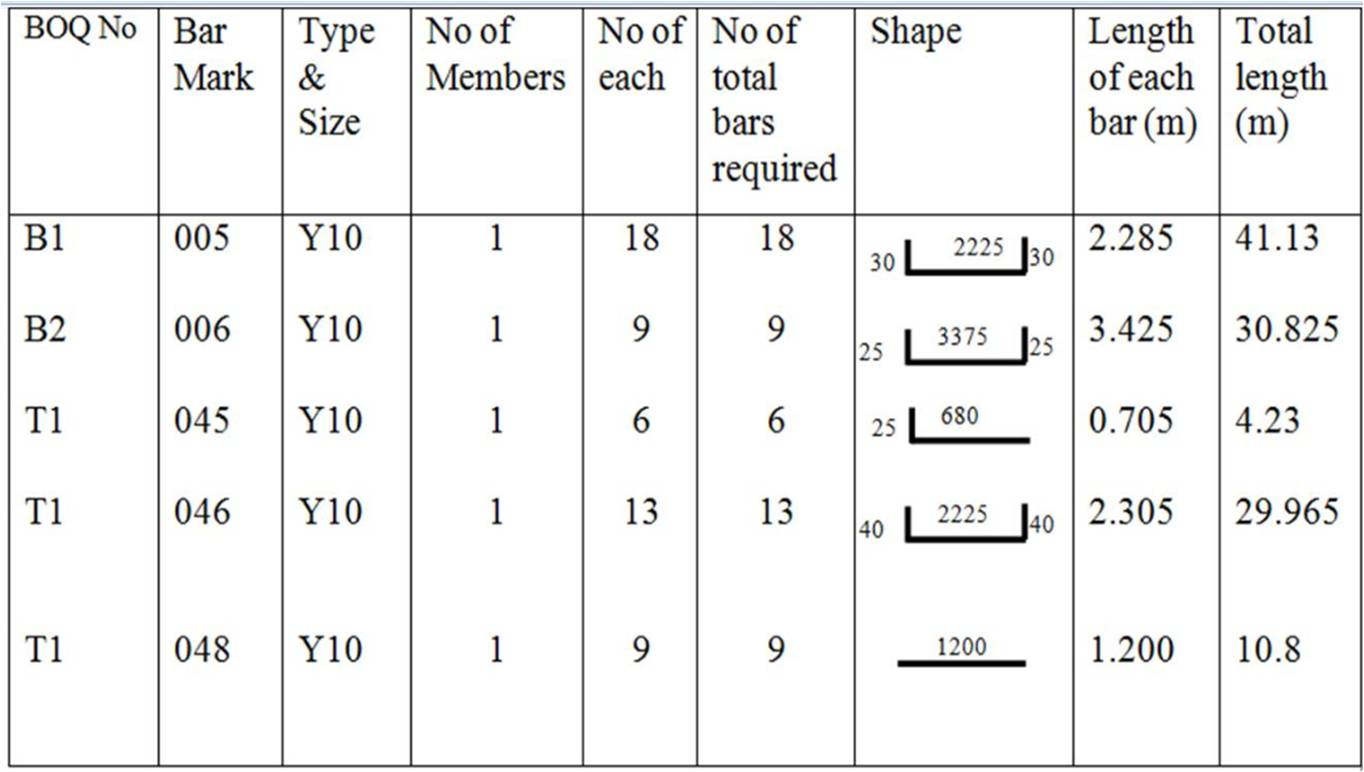
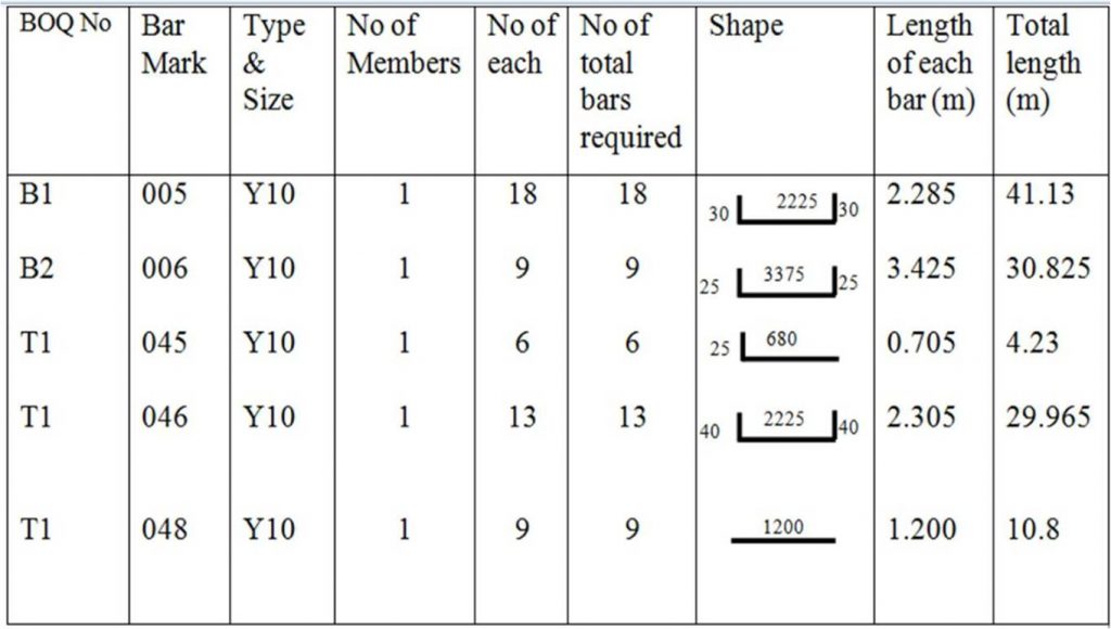
Table 3 : Bar schedule for Slab
- Bar schedule for some other structures


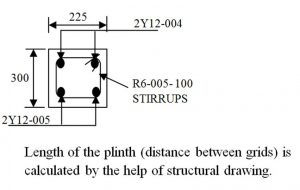
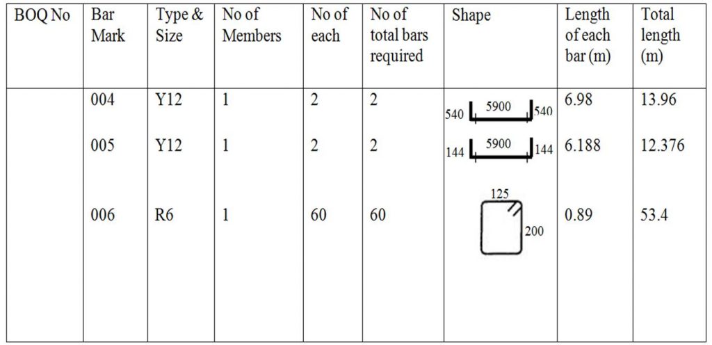
Table 4: Bar schedule for Plinth
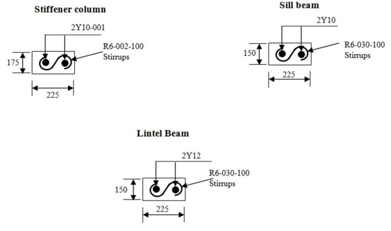
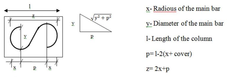
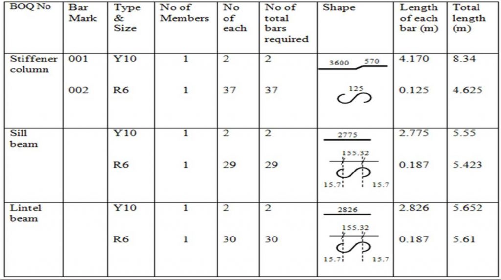
Bar schedule for Stiffener column, Sill beam and Lintel beam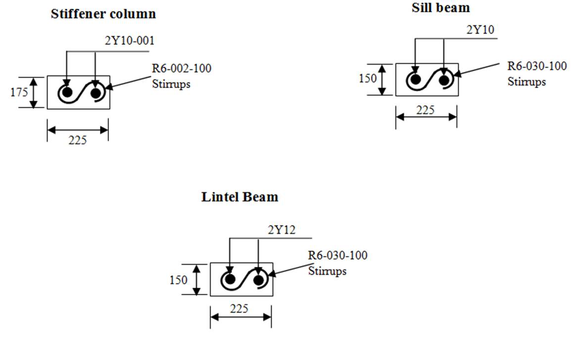

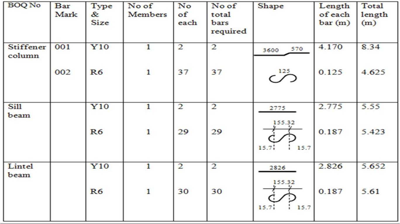
Table 5: Bar schedule for Stiffener column, Sill beam and Lintel beam
Great post — the detailed explanation of Bar Bending Schedule (BBS) preparation is very informative. I especially appreciate how it covers bar codes, cutting and bending processes, and tips to minimize bar cutting wastage. For anyone looking for Bar Bending services in Hyderabad, posts like this are really helpful for understanding the process and ensuring accurate reinforcement work.
ReplyDelete