Saturday, November 5, 2016

Quantity Surveyor

Though below mentioned terms can be easily familiarized by Professional Quantity surveyor within no time after he enter into real construction industry, it is useful for the students to understand the concepts & procedure completely. For the clear explanation purposes they are discussed in different headings.
Sample drawing
Sample drawing

A. Terms related to drawings


1. Tender drawings

These are the drawings given to the bidders at the tender time to price the blank BOQ. It should be read in line with specifications to proper pricing of the BOQ. For example sometimes supports are not mentioned in tender drawings but if it is provided in specification, bidder should consider the cost of that supports while pricing the particular item. Tender drawings & Specifications are very important in the post contract stage to deal with variations.

2. IFC Drawings

It is the short form of “Issued for construction”. This is the drawing is given by the consultant for construction purposes as well as preparation of shop drawings to the contractor. Some times for reference purposes and information purposes drawings shall be issued. They are known as “Issued for reference” (IFR) and “Issued for Information” (IFI) respectively.

3. Architectural Drawings & Structural Drawings

These two drawings decide the stability of the construction. As name suggests Architectural drawings are prepared by Architects & Structural drawings are prepared by Structural Engineers. Architects are the first people who make the client’s requirement in paper. Structural engineers make sure that Architect’s design safe and structurally secure. Both the drawings are meaningless without each other.

4. Interior Design Drawings (ID drawings)

It provides the details or the interior structure of the construction project. For the commercial building projects it adds value. Proper coordination with other trades is very vital for deliver quality interior to the project.

5. Shop drawings

It is prepared by the service provider. Sometimes by Sub-contractor or supplier. The purpose of the shop drawings is to give assistance to the people who are doing the actual work at site. It has more details than other construction drawings. When MEP Sub-contractor makes shop drawings, he has to refer the IFC, ID drawings, Architectural Drawings & Structural Drawings proper the proper coordination.

6. Request for Information (RFI)

This is very common term which is used in construction industry. When a contractor is making the shop drawings, if he found a discrepancy he shall write to the consultant for clarification. That is known as RFI. The response shall be used for the continuous process.

7. As-built drawings

As name suggests these are the drawings prepared by the contractor after the execution of the works at site. These drawings reflect the actual construction of the project. These can be used for the final account purposes as well as the maintenance purposes.
It is very important to know about these type drawings for QS since he has to deal with the variations to the contract. Simply any changes to tender drawings, specifications shall be known as variations. (To be discussed in detail).

Quality Control (Pengendalian Mutu)

Dalam rekayasa dan manufaktur, pengendalian mutu atau pengendalian kualitas melibatkan pengembangan sistem untuk memastikan bahwa produk dan jasa dirancang dan diproduksi untuk memenuhi atau melampaui persyaratan dari pelanggan maupun produsen sendiri. Sistem-sistem ini sering dikembangkan bersama dengan disiplin bisnis atau rekayasa lainnya dengan menggunakan pendekatan lintas fungsional. ISO 9001:2008 dan TQM (Total Quality Management) adalah contoh standar dan pendekatan yang digunakan untuk pengendalian mutu.

Pengendalian Mutu

Pengendalian mutu (Quality Control), atau QC untuk akronimnya, adalah suatu proses yang pada intinya adalah menjadikan entitas sebagai peninjau kualitas dari semua faktor yang terlibat dalam kegiatan produksi. Terdapat tiga aspek yang ditekankan pada pendekatan ini, yaitu:
1. Unsur-unsur seperti kontrol, manajemen pekerjaan, proses-proses yang terdefinisi dan telah terkelola dengan baik, kriteria integritas dan kinerja, dan identifikasi catatan.
2. Kompetensi, seperti pengetahuan, keterampilan, pengalaman, dan kualifikasi.
3. Elemen lunak, seperti kepegawaian, integritas, kepercayaan, budaya organisasi, motivasi, semangat tim, dan hubungan yang berkualitas.
Lingkup kontrol termasuk pada inspeksi produk, di mana setiap produk diperiksa secara visual, dan biasanya pemeriksaan tersebut menggunakan mikroskop stereo untuk mendapatkan detail halus sebelum produk tersebut dijual ke pasar eksternal. Seseorang yang bertugas untuk mengawasi (inspektur) akan diberikan daftar dan deskripsi kecacatan-kecacatan dari produk cacat yang tidak dapat diterima (tidak dapat dirilis), contohnya seperti keretak atau kecacatan permukaan. Kualitas dari output akan beresiko mengalami kecacatan jika salah satu dari tiga aspek tersebut tidak tercukupi.
Penekanan QC terletak pada pengujian produk untuk mendapatkan produk yang cacat. Dalam pemilihan produk yang akan diuji, biasanya dilakukan pemilihan produk secara acak (menggunakan teknik sampling). Setelah menguji produk yang cacat, hal tersebut akan dilaporkan kepada manajemen pembuat keputusan apakah produk dapat dirilis atau ditolak. Hal ini dilakukan guna menjamin kualitas dan merupakan upaya untuk meningkatkan dan menstabilkan proses produksi (dan proses-proses lainnya yang terkait) untuk menghindari, atau setidaknya meminimalkan, isu-isu yang mengarah kepada kecacatan-kecacatan di tempat pertama, yaitu pabrik. Untuk pekerjaan borongan, terutama pekerjaan-pekerjaan yang diberikan oleh instansi pemerintah, isu-isu pengendalian mutu adalah salah satu alasan utama yang menyebabkan tidak diperbaharuinya kontrak kerja.

Pengendalian Mutu Total (Total Quality Control)

"Pengendalian mutu total", disebut juga sebagai manajemen mutu total, merupakan suatu pendekatan yang melampaui teknik-teknik pengendalian mutu statistik biasa dan metode-metode peningkatan mutu. Pendekatan ini menyiratkan gambaran secara lengkap dan evaluasi ulang dari spesifikasi-spesifikasi dari produk, tidak hanya mempertimbangkan fitur-fitur terbatas yang dapat diubah-ubah dalam produk sebelumnya. Jika spesifikasi asli tidak mencerminkan persyaratan mutu yang benar, maka kualitas dari spesifikasi tersebut tidak dapat diinspeksi atau (bahkan) diproduksi menjadi produk. Misalnya, desain dari sebuah bejana tekan harus mencakup tidak hanya material dan dimensi, tetapi juga bagaimana tentang pengoperasiannya, dampak penggunaannya terhadap lingkungan , faktor-faktor keamanan, keandalan dan persyaratan-persyaratan kemampu-rawatan, dan dokumentasi dari temuan-temuan tentang persyaratan-persyaratan tersebut. Manajemen Mutu Total/ Total Quality Management (TQM) mengacu pada metode manajemen yang digunakan untuk meningkatkan kualitas dan produktivitas dalam organisasi bisnis. TQM adalah pendekatan manajemen yang komprehensif yang bekerja horizontal di seluruh organisasi, yang melibatkan semua departemen dan karyawan, dan memperluas baik ke "belakang" maupun ke "depan", termasuk bagi para pemasok dan klien. TQM hanya salah satu dari banyak akronim yang digunakan untuk menamai sebuah sistem manajemen yang berfokus pada mutu. Akronim lainnya termasuk CQI (Continuous Quality Improvement/ Peningkatan Putu Berkelanjutan), SQC (Statistical Quality Control/ Pengendalian Kualitas Statistik), QFD (Quality Function Deployment), QIDW (Quality in Daily Work/ Kualitas dalam Pekerjaan Sehari-Hari), TQC (Total Quality Control/ Pengendalian Mutu Total), dll. Seperti halnya pada sistem-sistem diatas, TQM menyediakan kerangka-kerangka kerja untuk menerapkan produktivitas yang lebih berkualitas dan inovatif secara efektif yang dapat meningkatkan profitabilitas dan daya saing organisasi .

Pengendalian Mutu dalam Manajemen Proyek

Dalam manajemen proyek, kontrol mutu membutuhkan seorang manajer proyek dan tim proyek untuk memeriksa pekerjaan yang telah dicapai untuk memastikan keselarasan antara pekerjaan yang telah terselesaikan dengan ruang lingkup proyek. Dalam praktiknya, pekerjaan-pekerjaan proyek biasanya memiliki tim khusus pada sistem pengendalian mutu yang berfokus pada daerah ini.

Bar Bending Shedule

Reinforced concrete is the most commonly used structural material in engineering construction. Although concrete is strong in resisting compressive stress, it is weak intention. Hence to withstand tensional stresses, steel is need in concrete. The reinforcement in concrete may be simple bars or rods bend and tied to a given schedule with stirrups. The nominal diameters of bars used at site were Y10, Y12, Y16, Y20, Y25 and R6.
Steel is supplied in two basic types.
1. Mild steel (250 N/mm2)
2. Tor steel (460 N/mm2)
  • Bar code            
Indication of Reinforcement in Drawings
Engineering drawings is a language to communicate with details. Therefore there is a standard to indicate reinforcement in drawing such as,
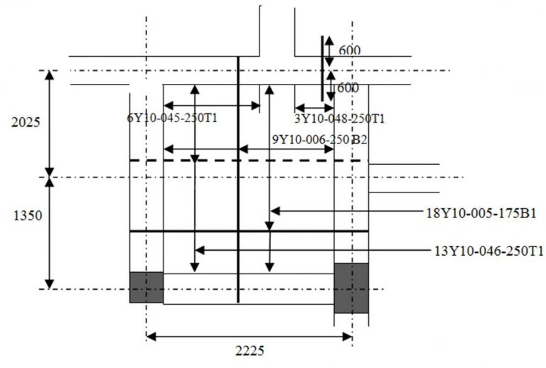
5Y10- 001- 150:-Which means 5 Number of Tor steel, 10mm Diameter, Bar mark 001, At 150mm CRS. At                                                      bottom face.
Bar location can be vary as follows:
Notation for Slab-
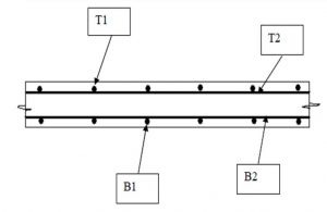
T1 -Top outer layer, T2 -Top second layer
B1 -Bottom outer layer, B2 -Bottom second layer
  • Cutting and Bending of Bars
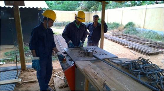
      There is a steel yard in the site for storing, cutting and bending of bars. Reinforcement bars are cut into required lengths and bent into required shapes shown on the bar schedule either manually or by means of machinery.
       In manual operations, laborers used the bar bending bench on which strong nails are fixed and GI pipes with suitable lengths to bend the bars. That is used for smaller diameter bars. For bending of larger diameter bars, bar bending machine is used. After bending all reinforcement bars were bundled and clearly numbered according to the bar mark so that steel fixers will not face any difficulty when fixing them.
Picture1
Fig.1 :- Bar bending work
  • Prepare bar schedule (important considerations)
 Reinforcement Bar Schedule
      Reinforcement Bar Schedule is prepared in a standard manner. The bar bending schedule should be prepared and it should be submitted to the steel bar steel yard to cut and to bend the bars for purposes, because bar bending schedule is the simplest of details what is in the drawings which can easy to under stand for bar benders. It contains all the details needed for fabrication of steel.Those details are bar mark, bar type and size, number of units, length of a bar, shape code, distance between stirrups (column, plinth, beam) etc.
Advantages of the Bar Schedule:
  • By preparing a bar schedule, and arranging them according to the lengths, it will lead to an economical bar cutting, reduce the bar cutting wastages.
  • It is easy to manage the reinforcement stock required for identified time duration.
  • It will help to fabrication of R/F with structure.
Calculating weight of the steel
 While prepared the bar schedule, we used the unit weight of reinforcement bar.
Nominal Diameter of the bar (mm)Unit weight (kg/m)
R60.222
R100.610
T100.617
T120.888
T161.580
T202.469
T253.858
T326.313
Table- Unit weight of the bar
It is necessary to be careful about length when preparing bar schedules. In case of bending, bar length will increased at the bending positions.
  • Minimization of bar cutting wastage
 In the site several steps were adopted for that purpose. Those are, Use of 12m long r/f bars rather than using shorter bars. For example 6m bars off cuts of 12m bars were used to prepare stools, separators etc.
  • Off cuts of larger diameter (25mm) bars-for spacer bars
  • Off cuts of smaller diameter (10mm) bars-for stools
  • Lapping
     Lapping is required when a bar isn’t long enough or a joint is required. Bars may be deliberately left short for constructability and transportation concerns. The preferred method of lapping where the two bars overlap each other for some minimum distance. This distance is called Lap length. These two bars are in physical contact and wired together. It does not represent an actual bend in the bar.
Picture20
Fig 2: Lapping and cranking detail
  • Other material used In Reinforcement Works
Binding Wires
R/f bars are jointed with using wires which is called “binding wires”. Hackers are used to bind these wires.
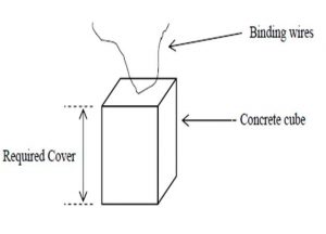
Cover Blocks
     They were made up of 1:3 ratio of cement mortar. Cover blocks should be immersed in water for 28 days to get the maximum strength.All the beams were checked to ensure adequate cover blocks are provided to the bottom and sides of the beam reinforcementMain bars of the columns were adjusted to ensure the covering requirements before concreting. Stools of correct height were used to maintain the require gap between top and bottom reinforcement nets and cover blocks were also provided to bottom reinforcement.
Picture21
Fig 3: Cover blocks
Cover to Reinforcement
  • Concrete cover for steel bar is much necessary to protect the steel against corrosion (rusting) and to provide resistance against fire.
  • For R.C.C. Slab and staircase the cover is 20 mm.
  • For RCC column the cover (To stirrups) 30mm.
  • In case of underground structures the cover is 50 mm.
  • In case of beams in superstructure (To stirrups) the cover is 25mm.
  • In case of ground resting floor slab (Top surface) and retaining walls the cover is 50m.

  • Stirrups
       Stirrups will be required at areas of high shear, such as bearing points and below large point loads.  Increasing concrete beam spans, to reduce the need for additional piers, has resulted in the need for the use of steel stirrups. Concrete beams vary in depth.  The deeper the beam, the more shear capacity.  When the depth is not adequate, steel stirrups must be added to increase the shear capacity of the beam.
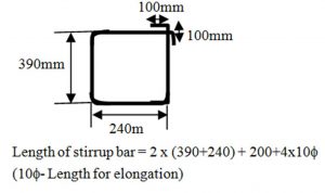
       These stirrups are usually one piece of steel that is bent into a rectangular shape. The stirrup typically wraps around the bottom and top bars of the beams. A designer should specify the size, spacing and location along the length of the beam where the stirrups are required.  In my site specify the stirrup dimensions in our section drawings, so that the stirrup can be manufactured prior to installation. The installer should be careful to fabricate the stirrup from one piece of steel and adequately overlap each end.
Picture22
Fig 4: Bar Schedule for stirrups
  • Stools
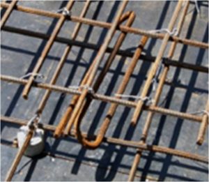
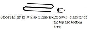
Stools are used to separate the top reinforcement mesh and bottom reinforcement mesh. Dimension of the Stools could be change as requirement. Those should be strength enough to bear the loads without changing the gap of two layers. 12 mm or 16 mm bars are used to make the stools.
Picture24Picture23
Fig 5: Stools
Important  points to be checked.
  • Size of the bar
  • Length of the bar
  • Location of the bar
  • Position of the bar
  • Number of bars
  • Lap lengths
  • Correct cover of reinforcements and cover blocks
  • Spacing (in slab reinforcements and stirrups)
  • Direction of the bars (in slabs)
  • Dimensions of the element thickness of a slab, depth and width of a beam, etc…)
Columns, Beams, Slab Reinforcement
  • Column Reinforcement
      The column reinforcement bars should be stared from the Footing. The upper column reinforcement bars are cranked at the laps and connected. Special care should be taken in this to ensure the lap lengths. After erection of main reinforcements, cover blocks were attached to column reinforcements to maintain the required cover for column reinforcement. Most of Columns centers were located at intersections of grid lines.
Stirrup spacing
       According to the Column reinforcement details drawing the reinforcement detail for a typical internal Column, from to basement to ground floor is as follows.
       Column stirrups were tightened up to beam bottom level and rest is tightened once beam reinforcement is fabricated. So Bar benders was instructed how to provide the stirrups. Mark the stirrup spacing from the basement floor level in the Column main bars with a chalk as follow the detail drawing.
E.g.:
Picture25Picture26
Fig 6:  Section of column Reinforcement
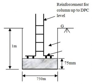
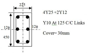
Bar Schedule for Footing, Column up to DPC and Column.
E.g-
Picture2
Footing
Size – 1000 x 1000 x 250
R/f Details – Y10 at 225 C/C (B) Both ways
Picture3
Table 1: Schedule for Footing, Column up to DPC and Column
  • Beam Reinforcement
   Beam is a horizontal structural member resting on two or more supports. It is used to transfer the load to the columns.Beam reinforcements are arranged after the construction of beam and slab formwork.
The method adopted for the arrangement of beam reinforcements is as follows:
    First the top most reinforcement bars are hung over the beam formwork and then the stirrups are placed and bound at correct positions. Thereafter the bottom reinforcement bars are placed and bound to the stirrups. After that the rest of the reinforcement bars and tension bars are inserted into the cage according to structural drawings. Then cover blocks are fixed to bottom and side reinforcements before placing the concrete.
Consideration for give lap length
Picture27
Fig 7: Reinforcement for beams
    Top reinforcement of the beam shall be lapped at the middle of the span of between two supports. Bottom reinforcement of the beam shall be lapped at the end of the span of the two supports. Considering the region where the maximum bending movement is existing.
       Lapping is did the place which the tension is didn’t act. Normally 2/3 of the length is choosing for lapping. When lapping top & bottom re-bar, it is better to follow the following method.Otherwise, it might cause to reduce the concrete covering thickness of the topmost& bottom most slab reinforcement.
Picture28
Fig 8: Reinforcement  for beams
Anchorage (bond) in concrete
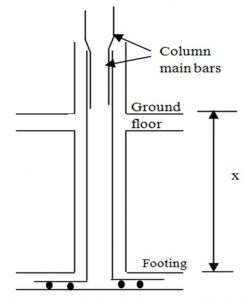
Because the actual bond stress varies along the length of a bar anchored in a zone of tension. The main requirement for safety against bond failure is to provide a sufficient extension of the length of the bar beyond the point where the steel is required to develop its yield stress and this length must be at least equal to its development length. However, if the actual available length is inadequate for full development, special anchorages must be provided, such as bends, hooks.
E.g- (Anchorage length 45 d (for top bars),12 d (for bottom bars)) where “d”, “Ø”  is diameter of the Bar.
Anchorage length Calculation
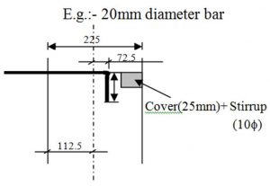
E.g.:-  20 mm diameter bar
Picture29
Fig 9: Anchorage length
Bending length = 112.5- (Cover (25 mm)+ Stirrup (10 Ø))
= 72.5mm
Anchorage length (x) = 45 x diameter of the bar(20 Ø)
= 827.5 mm
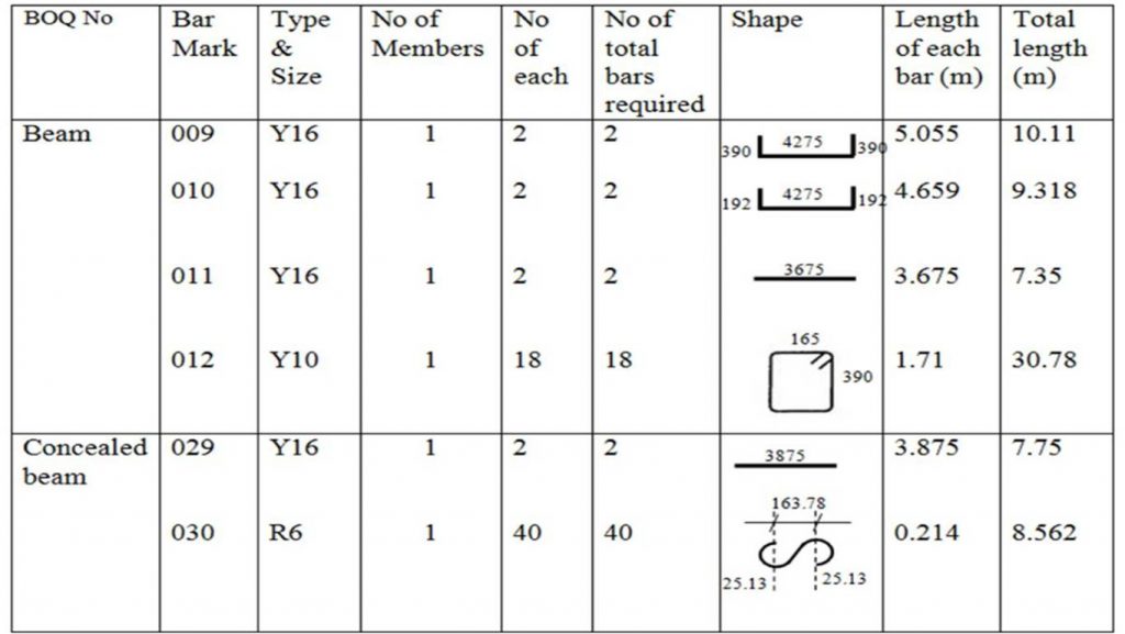
Bar schedule for Beam
Picture6
Picture7
Table 2: Bar Schedule for Beam
  • Slab Reinforcement
Slab reinforcement is the most important part of the structure. It is important to have an idea on slab reinforcement detailing. Following basic thing could be studied in drawing on slab reinforcement detailing.

Distribution bar reinforcement

Small diameter bars, usually at right angles to the main reinforcement, intended to spread a concentrated load on a slab and to prevent cracking.Standard method used for indicated the slab top & bottom reinforcement.
Picture30
First step of the fixing of slab reinforcement was placed the bottom most R/F (B1) of the slab. Before placing the re-bar, correct spacing given in the detailing drawing were marked by using piece of choke on the slab formwork. After placed the (B1) R/F then placed the (B2) R/F and bound both R/F layers together by using binding wire. Then cover blocks for bottom most R/F were fixed. Finally, Top R/F (T2), Topmost R/F (T1)& distribution bars were placed according to the drawing and fixed together by using binding wire. Then Stools were fixed to separate the both top & bottom R/F net as fulfilled the thickness.


Fig 10:  Reinforcement of a slab
Bar crank
Bar cranking is the process of bending up the bottom steel bars in upward direction. It is mainly to prevent upward bending moment near the joint. Also useful for attaching stirrup bar effectively. Cranking is also used in two way slabs.
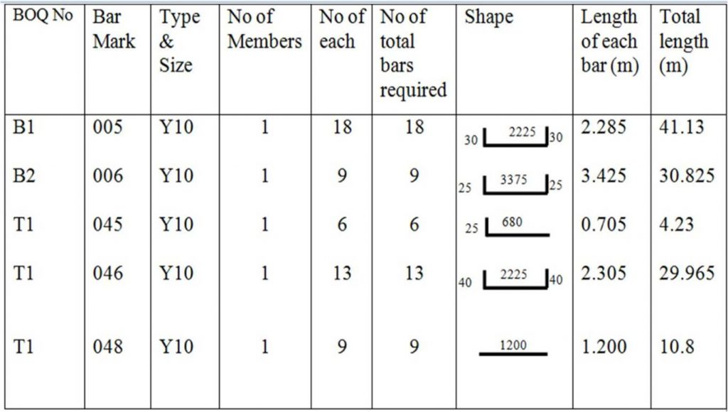
  • Bar schedule for Slab
Picture8
Picture9
Table 3 : Bar schedule for Slab
  • Bar schedule for some other structures
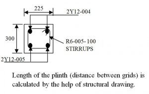
 Bar schedule for Plinth 
Picture4
Picture33
Table 4: Bar schedule for Plinth
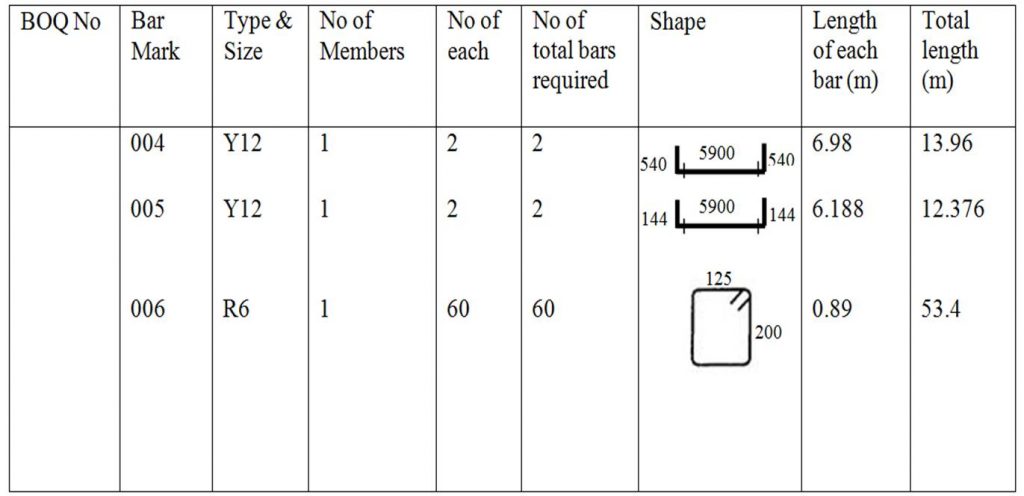
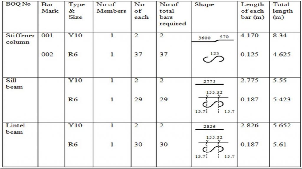
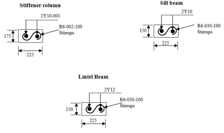
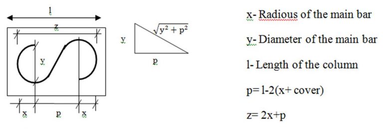
Bar schedule for Stiffener column, Sill beam and Lintel beam
Picture10
Picture11
Picture31
Table 5: Bar schedule for Stiffener column, Sill beam and Lintel beam
Rencana Anggaran Biaya

Rencana anggaran biaya bangunan atau sering disingkat RAB adalah perhitungan biaya bangunan berdasarkan gambar bangunan dan spesifikasi pekerjaan konstruksi yang akan di bangun, sehingga dengan adanya RAB dapat dijadikan sebagai acuan pelaksanaan pekerjaan nantinya.


Untuk menghitung RAB diperlukan data – data antara lain:
  • Gambar Rencana Bangunan.
  • Spesifikasi Teknis Pekerjaan yang biasa disebut juga sebagai RKS ( Rencana Kerja dan syarat – syarat )
  • Volume masing – masing pekerjaan yang akan di laksanakan.
  • Daftar harga bahan bangunan dan upah pekerja saat pekerjaan di laksanakan.
  • Analisa BOW atau harga satuan pekerjaan.
  • Metode kerja pelaksanaan.
selanjutnya kita akan mencoba menghitung suatu rencana anggaran biaya pekerjaan bangunan.
Cara menghitung rencana anggaran biaya bangunan adalah sebagai berikut:
misalkan sebuah pekerjaan plesteran  1 pc : 4 ps tanpa acian pada pasangan bata 2 muka dengan gambar kerja sebagai berikut:
langkah pertama adalah menghitung volume pekerjaan plesteran.
v plesteran= 2 m x 3 m x ( 2 muka ) = 12 m2
berikutnya kita mencari tabel analisa BOW atau analisa harga satuan pekerjaan:
Analisa  untuk 1 m2 pekerjaan plesteran 1 pc : 4 ps adalah
  • 0.2170 zak semen
  • 0.02830 m3 pasir pasang
  • 0.0125 mandor
  • 0.0200 kepala tukang
  • 0.2000 tukang batu
  • 0.2500 pekerja
selanjutnya  kita mencari harga bahan dan upah untuk analisa pekerjaan diatas, contohnya sebagai berikut ( harga disini hanya perkiraan untuk lebih tepatnya bisa di survey di toko ):
  • semen = Rp. 59.000 / zak
  • pasir pasang = Rp. 150.000,00 / m3
  • mandor = Rp. 50.000,00 / hari
  • kepala tukang = Rp. 45.000,00 / hari
  • tukang batu = Rp. 40.000,00 / hari
  • pekerja = Rp. 35.000,00 / hari
langkah berikutnya adalah mengalikan antara analisa harga satuan dan harga bahan/ upah sebagai berikut
  • semen =0.2170 x Rp. 59.000= Rp. 12.803,00
  • pasir pasang =0.02830 x Rp. 150.000,00= Rp. 4.245,00
  • mandor =0.0125 x Rp. 50.000,00= Rp 625,00
  • kepala tukang = 0.0200 x Rp. 45.000,00= Rp. 900,00
  • tukang batu = 0.2000 x Rp. 40.000,00= Rp. 8.000,00
  • pekerja =0.2500 x Rp. 35.000,00= Rp. 8.750,00
  • jadi jumlah harga total 1m2 plesteran adalah Rp.35.323,00
setelah diketahui harga per 1 m2 plesteran adalah Rp.35.323,00 maka langkah terakhir adalah mengalikanya dengan total volume plesteran yang sudah dihitung sebelumnya yaitu 12 m2
Jadi total harga plesteran adalah 12 x 35.323 = Rp.423.876,00 biasanya terus dibulatkan Rp.423.000,00
terbilang ( empat ratus dua puluh tiga ribu rupiah).
begitulah kurang lebih caranya.

Manajement Proyek

Management Proyek adalah ilmu yang mempelajari dan mempraktikkan aspek-aspek manajerial dan teknologi industri konstruksi. Manajemen konstruksi juga dapat diartikan sebagai sebuah model bisnis yang dilakukan oleh konsultan konstruksi dalam memberi nasihat dan bantuan dalam sebuah proyek pembangunan.
Construction Management Association of America (CMAA) menyatakan bahwa ada tujuh kategori utama tanggung jawab seorang manajer konstruksi, yaitu perencanaan proyek manajemen, manajemen harga, manajemen waktu, manajemen kualitas, administrasi kontrak, manajemen keselamatan dan praktik profesional.
Peranan Manajemen Konstruksi dalam Industri Konstruksi adalah layanan yang sangat baik yang disediakan untuk mengkoordinasikan dan mengkomunikasikan seluruh proses konstruksi. Sebagai manajer proyek konstruksi akan menangani semua tahap konstruksi proyek Anda. Pada tahap pra-konstruksi, kita akan melakukan semua yang diperlukan studi kelayakan dan penelitian. Kemudian datang desain dan perencanaan. Setelah spesifikasi arsitektur dan tujuan penjadwalan yang didefinisikan dengan baik, pekerjaan dilanjutkan oleh pembangun dan kontraktor untuk memulai membangun aktual bawah pengawasan yang ketat kami. Menekankan pada independen dari para profesional lain yang terlibat dalam konstruksi. netralitas ini memungkinkan untuk secara objektif dan tidak memihak menyarankan klien pada pilihan consultans dan kontraktor, yang memungkinkan klien untuk mendapatkan manfaat maksimal.

Saturday, April 21, 2012

Kisah syekh Abdul Qodir jaelani

Kisah syekh Abdul Qodir jaelani : ada seorang Nasrani berdalih bahwa Isa Almasih lebih Hebat dari kanjeng Nabi Muhammad, dengan berkata: ان عيسى كان يخي الموثى Artinya: sesungguhnya Isa almasih bisa menghidupkan orang mati. maka tuan Syekh mengajak sang Nasrani tersebut kesalah satu makam dan menunjuk kuburan yg sudah ratusan Tahun, sambil berkata : اني لستُ بنبي بل من اثباع محمد صلى الله عليه وسلم. ان احييت ميتا اتؤمن بنبينا محمد صلى الله عليه وسلم. Artinya: Sesungguhnya saya bukanlah Nabi, Melainkan Hanya Pengikut Nabi Muhammad Salallahu'alaiwasalam. sungguh saya bisa mengihupkan orang mati hanya karena iman kepada Muhammad salallahu'alaihiwasalam. maka sang Nasrani menjelaskan bahwa isa almasih menghidupkan orang mati dgn berkata : قم بإذن الله artinya : dengan izin Allah, (ini mayat) bangunlah.. maka syekh Abdul Qodir mengeluarkan Karomahnya dgn menghidupkan orang sudah di kubur Ratusan Tahun dengan berkata : قم بإذني artinya: dengan izin-Ku, (ini Mayat) bangunlah.. Akhirnya mayat yg sudah di kubur ratusan Tahun itu bangkit dan hidup kembali dengan menari-nari. disaat sang Nasrani tersebut setelah menyaksikan Karomah Tuan syekH, akhirnya ia menima ISLAM.. (MANAQIB Syekh siti Jenar, di tukil dalam kitab "Jawahirul Ma'ni" hal :17-20, karya Syekh jauhari Umar pasuruan JATIM)

INTI SEJATI MENGGAPAI RIDHO

INTI SEJATI MENGGAPAI RIDHO Bismillahirrahmanirrahim Dalam cintaku yang sederhana kepada para saudaraku yang tengah menjalani hidup menggapai kesempurnaan hidup yang diidam idamkan.... berbahagialah kalian dalam kobaran gairah Cintanya........ sedikit rasa kasih dan sayang ini terurai dalam huruf2 yang kurangkai sedemian rupa... untuk kalian yang kasihi dan kusayangi... Ijinkan sedikit bertanya tentang perolehan ridho: Apakah masih tidak yakin kalian mampu mencapai cahaya Ilahi? Pusat Cahaya, Cahaya Diatas Cahaya??? sesuatu yang Sulit dicapai? Bukan dongeng ataupun mitos jika tidak pernah menggapainya, bukan pula ilusi, bukan pula hayalan, bukan pula pencapaian yang harus dengan laku2 nyeleneh dan ruwet.... Ambillah sebatang korek api nyalakan... (sendirian) Ambillah sekardus korek api... nyalakan beberapa diantaranya...(berbarengan) Itulah nikmat jamaah... Inti Karomah, ragam Fadhilah yang terdapat dari kebersamaan... Sering2lah berjamaah, merski jasad tidak pernah ngumpul, namun sambung menyambunglah dalam do'a .... doakan satu sama lain. karena sesungguhnya kalian bersaudara, bahkan kalian adalah satu negri, satu kota, bahkan satu tubuh... semoga kalian bisa saling meridhoi.... laksanakan dengan niyat yang Tulus Ikhlas SALAMUN QOULAM MIRROBBIRROHIEM Alhamdulillah Semoga Kalian diridhoi Allah Subhanahu wata'ala Amien Yarobbal'alamin R-A-H-A-Y-U